1. Introduction
When splicing optical fibre, the environment can have a significant impact on the ultimate loss result. This can be the result of things like temperature variations, moisture, airborne contamination, vibration or workstation instabilibility. This is particularly an issue in harsh environments, but can also play a factor in other more controlled environments. In this article, we’ll talk about the factors that impact splice loss, and what you can do to ensure you minimise splice loss and deliver consistent results, even in harsh conditions.
2. What Drives Splice Loss
Splice loss comes from a number of places. The fibre itself, the way it is handled in the field, and the equipment used to splice it. Understanding both gives you control over those factors, and ultimately over the splice loss. There are two main categories of factors that impact splice loss - intrinsic and extrinsic.
Intrinsic factors are those inside the glass. Mode field diameter variation, mismatch between fibres that produce a small step in the optical path, and that step turns into attenuation. Core concentricity also matters. A core that drifts off centre increases sensitivity during alignment, and is likely to have higher splice loss. Bend-insensitive fibres behave well under installation strain, though their trench structure changes how the core captures light. None of these characteristics are visible in the field. You see them only in the numbers printed on the data sheet or in the consistency of your loss readings.
Extrinsic factors come from the splice process and the equipment used. With modern, high quality fibre, this is where most loss originates. A poor cleave introduces endface angle or micro-fractures that scatter light. Contamination sits on the endface and burns during the arc. Contamination in the v-grooves causes misalignment that shifts the cores by microns and creates a permanent optical step. Residual strain from routing or closure assembly alters how the splice sits once the sleeve cools. All of this adds to your loss budget.
A good fusion splice has low loss. Technicians should expect around 0.01 to 0.02 dB with a quality core-alignment splicer for single-mode work when both intrinsic and extrinsic factors are optimised. Core alignment splicers such as FiberFox Mini 5C+ Premium operate well in this range because they view and align the core directly. They do this through the use of additional motors to compensate for alignment when factors like dust or poor fibre concentricity would otherwise cause misalignment. Cladding alignment units can drift higher when fibres vary in geometry, like low quality fibres or fibres of different types, or when contamination in the v-grooves causes fibres to not sit exactly right.
Splice loss becomes predictable once you understand these mechanical and optical drivers. They form the foundation for consistent loss results across outdoor, industrial, and temperature-exposed sites where good practice is the only stability you have.
3. Environmental Forces That Increase Loss
Harsh environments amplify every weakness in the splice setup. For example, temperature changes impact how the fibre reacts during the arc process. Cold glass contracts and stiffens, which alters how the core deforms under heat. High humidity introduces moisture onto the stripped fibre that flashes during the arc and leaves residue. Heat softens coatings and makes stripping inconsistent. All of it can show up as higher loss.
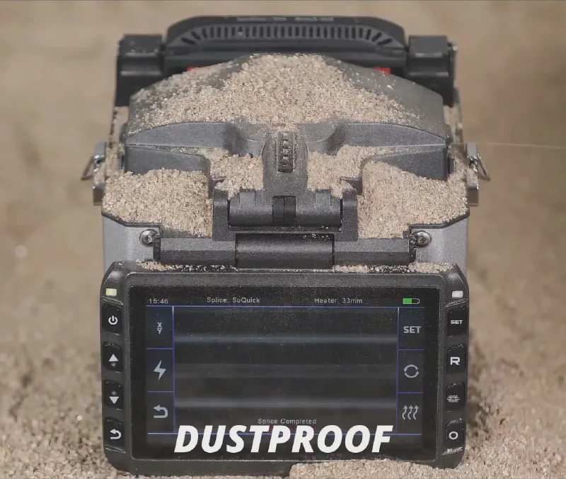
Wind and airborne dust cause problems from another angle. A light breeze across the splice cools the arc unevenly and destabilises the melt. Even the breeze from airflow in a datacentre can impact the splicing process. In many environments, dust settles on the bare fibre just after cleaving. You only notice the effect when the loss jumps by a small margin for no clear reason. These are mechanical contaminants, not optical ones, and they behave unpredictably. Even small specs of dust in the v-grooves can cause misalignment, and ultimately additional loss.
Mechanical shock matters as much as contamination. A work table that vibrates under traffic or machinery shifts the fibre during alignment. Even a few microns of movement pushes a core alignment splicer away from its ideal point. You tend to notice this most when working off ladders, manholes, or elevated platforms. Any instability in the fixture or workstation cause cause increased splice loss before the arc even fires.
Storage conditions also feed into the problem long before the splice. Fibre that sits in a hot vehicle softens at the coating. Rapid cooling later changes how it strips and cleaves. Moisture inside splice sleeves or trays evolves into fogging when the heater runs. Older fibre stored incorrectly becomes brittle and exhibits different stripping performance and performance under bending.
Low loss in harsh environments comes from controlling these variables. Shield the splicer, stabilise the work surface, and keep fibre dry and clean. When conditions are poor, expect the numbers to also be poor. Core alignment units such as FiberFox Mini 5C+ Premium handle these conditions with stronger alignment technology, but they still rely on a stable environment to reach the 0.01 to 0.02 dB range expected of quality fusion splicing.
4. Preparing Fibre for Repeatable Low Loss
Given that many of the factors we have discussed are out of the operators control, hygiene is one of the most important elements that can be controlled. That good hygiene starts with ensuring that the splicer itself is always cleaned and maintained. Ensuring that the splicer is serviced regularly ensures that it is in top condition as a starting point.
Onsite, it’s critical that the splicer be protected from dust and contaminations. Always close the wind protector when the splicer is not in use, and maintain good v-groove hygiene. Even small contaminants in v-grooves (especially on cladding alignment splicers) can cause increased loss. When you begin work for the day, perform an arc calibration. This will calibrate the arc for the current conditions, ensuring the splicer is optmised for the environment in which you are operating.
Good discipline during fibre stripping, cleaning and handling of fibre minimises (but does not remove) the impact of some of those factors. Fibre should always be prepared using quality fibre optic tooling. Likewise, it must always be cleaned (where possible) using 100% isopropyl alcohol and handled with care as it is cleaved and inserted into the splicer. Any contamination introduced after cleaning can impact both direct alignment (by causing the fibre not to sit in the v-groove correctly) or influencing the arc (by causing the arc to burn off contaminants, rather than fusing the fibres).
5. Cleaving and Why the Angle is Important
An often overlooked part of the fusion splicing process is the cleaving of the fibre. This process uses a diamond blade to neatly cleave off the end at as close to 90 degrees as possible. Many cleavers work on the same principle, and often claim to be high precision. However, they are deceptively complex devices. Cleaving with such a fine target, across a range of different fibre types and manufacturers, requires a high precision device that maintains consistent performance cleave after cleave. Some cheap cleavers are machined from cheap materials, feature low grade blades, and generally perform poorly.
If you compare the build, finish and result to a high quality cleaver like the FiberFox Mini 60A+ High Precision Cleaver you will see that the difference in quality makes a big difference in consistent cleave angle. Many cleavers today have a similar feature set, and this is not really the differentiator for splice performance - it’s build quality, usability and result that count.
What is important, though, is the cleaning and maintenance of the cleaver. Ensuring that fibre sharps and kept safely (preferably in an integrated sharps bin or collector), and ensuring that the cleaver pads and blade are clean of unwanted dust, fibres and contamination are really critical to ensuring a good cleave angle. Contamination on the cleaver can throw the fibre out of alignment, meaning the angle is off, leading to a bad splice result.
6. Choosing the Right Fusion Splicer
Splicers come with different technologies, but can be broadly categorised as either core-alignment or cladding alignment. Core alignment splicers, like the FiberFox Mini 5C+ Premium use improved technology to align the core on each side directly. This splicer specifically uses Automatic Optical Core Analysis & Tracking (AOCAT), in which additional motors and cameras inspect the fibre, identify the core and align it precisely to the opposing core. Other splicers, like the FiberFox Mini 4S+ Premium are less advanced (and so, more cost effective) and only perform alignment of the cladding (the 4S+ actually performs Active Cladding Alignment, so it technically sits in a class between core-alignment and regular cladding alignment splicers).
The impact on the two methods on splice loss depends on the intrinsic and extrinsic factors. Because the core-alignment splicer identifies and moves the core to directly align it with the opposing side, it is much more capable of overcoming small issues like minor contamination or concentricity issues with the fibre. For cladding alignment splicers, they have limited ability to identify the core, and completely lack the motors used by a core-alignment splicer to perform that alignment. Accordingly, any contamination or fibre concentricity issues cannot be overcome by aligning the fibres. The take away is that cleaning is important regardless of splicer technology, but it is much more criticial in a cladding alignment splicer.
For field splicing where loss is critical, like core network splicing where one splice might affect thousands of subscribers, the core-alignment technology provides a consistently better result than cladding alignment. For less critical splicing, like FTTH drops where one splice might only affect one subscriber, cladding alignment can be a suitable option.
7. Splicer Setup for Harsh Conditions
Optimising the fusion splicer setup is part of the process fo consistent low-loss splices, particularly in variable conditions. This includes performing arc calibration, and selecting the correct splice and heating modes for your fiber types.
Arc calibration adjusts the arc power to suit current environmental conditions (temperature, humidity, altitude) and compensates for electrode wear or residue buildup. It ensures even melting of the fiber ends, preventing weak or over-fused splices that increase loss. The process typically involves loading clean prepared fibers, initiating the calibration menu, and letting the splicer perform test discharges while automatically adjusting parameters until optimal. Perform arc calibration at the start of each workday, after electrode replacement (every ~5,500 arcs on models like the FiberFox Mini 5C+ Premium), when moving to a new site with changed conditions, or if loss readings become inconsistent.
Setup also requires matching modes to fiber types. The FiberFox Mini 5C+ Premium supports common types including single-mode (SM: G.652, G.657), multi-mode (MM: G.651), dispersion-shifted (DS: G.653), non-zero dispersion-shifted (NZDS: G.655), and cut-off shifted (G.654). In many modern quality core-alignment splicers, like the FiberFox Mini 5C+ Premium, a built in “AUTO” splice program is included and does a reasonably good job. You may find that using a specific program to match your fibre type might result in lower splice loss. This is particularly true of specialty fibres like G.654.E, G.655 or other similar fibre types.
Combine arc calibration with thorough cleaning of V-grooves and electrodes, stable workstation setup, and proper mode selection to achieve repeatable results around 0.01–0.02 dB in single-mode splicing.
8. Conclusion
Low splice loss in harsh environments comes from discipline and splicer performance rather than luck. The physics of the glass set a baseline, though the outcome stays dominated by preparation, cleanliness, stability, and equipment choice.
Harsh conditions remove any margin you might have otherwise had. Dust, moisture, temperature, and vibration all show up as loss in one form or another. Crews who shield the splicer, stabilise the workstation, maintain their splicer, and calibrate the arc achieve predictable results even when the environment is poor. Core-alignment splicers make this easier, though they amplify the value of good field practice rather than replace it.
Consistent results around 0.01 to 0.02 dB reflect a controlled process. Fibre quality, cleaning practice, high quality cleaves, correct programs, and repeatable setup all form part of that process. When the process is consistently good, harsh environments become manageable variables and splice loss becomes an mamaged outcome rather than a surprise.